本帖最后由 zoologist 于 2024-11-17 11:09 编辑
HT513 是一款国产的D类单声道I2S 功放芯片。特别之处在于它支持通过 I2C 接口控制输出音量,因此可以在保证输出效果的情况下极大简化软件设计。
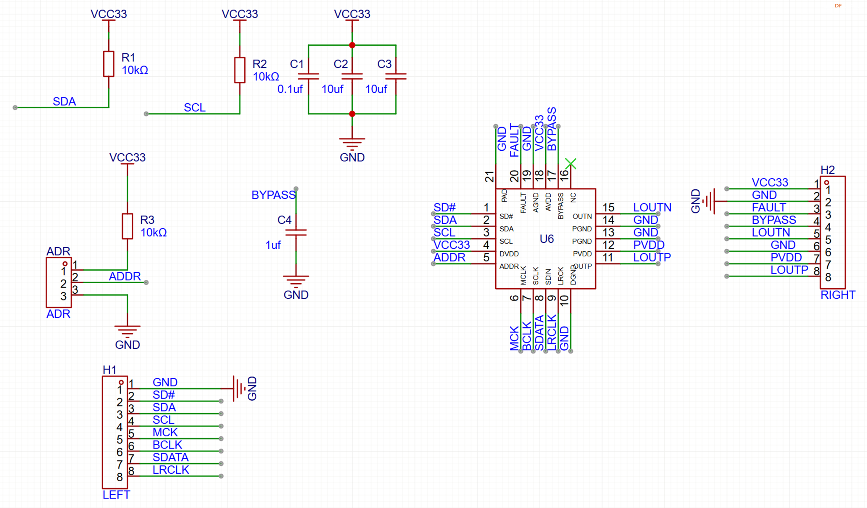
首先设计一个HT513的功能板,电路图如下:‘
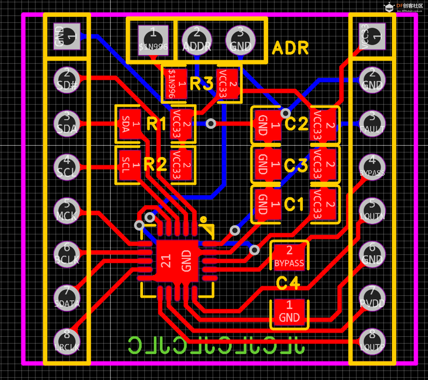
PCB设计如下:
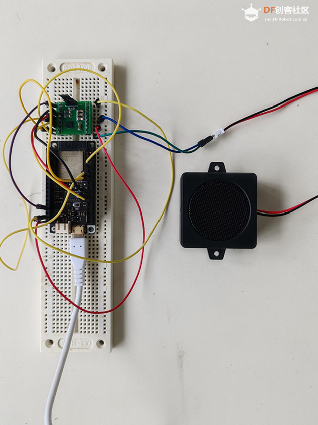
焊接完成后,可以直接在面包板上使用。
这次测试DFRobot的FireBeetle 通过 I2S 接口发送音频数据给 HT513, 最终通过喇叭将音频播放出来:
测试使用 AudioTools 库(Arduino-audio-tools-1.0.0 )。测试的代码是基于这个库自带的两个例程,一个是生成正弦波送至I2S 接口(streams-generator-i2s ),我们在这里测试评估 HT513 音量调整的功能;另外一个是播放存储在 Flash 中的WAV 文件(streams-memory_raw-i2 )。在例子的寄存上增加对于 HT513 初始化设定的代码。关键部分如下:
- #define HT513_ADDR_L 0x6c
- /**
- @brief ht513写寄存器
- @param addr 寄存器地址
- @param val 要写的值
- @retval None
- */
- void HT513_WriteOneByte(uint8_t addr, uint8_t val)
- {
- Wire.beginTransmission(HT513_ADDR_L);
- Wire.write(addr);
- Wire.write(val);
- Wire.endTransmission(true);
- }
-
- /**
- @brief ht513读寄存器
- @param addr 寄存器地址
- @retval 读取到的寄存器值
- */
- uint8_t HT513_ReadOneByte(uint8_t addr)
- {
- uint8_t temp = 0;
-
- Wire.beginTransmission(HT513_ADDR_L);
- Wire.write(addr);
- Wire.endTransmission(true);
-
- Wire.requestFrom(HT513_ADDR_L, (uint8_t)1);
- temp = Wire.read();
-
- return temp;
- }
在Setup() 中加入下面的代码:
- Wire.begin(21,22);
- // 设置 SD 为LOW
- HT513_WriteOneByte(0x12,0b11110000);
- // 设置数据格式为 I2S, 16Bits
- HT513_WriteOneByte(0x13, 0b00110000);
- // 调整音量
- HT513_WriteOneByte(0x16, 0b10100000);
- // 设置 SD 为LOW
- HT513_WriteOneByte(0x12,0b11110100);
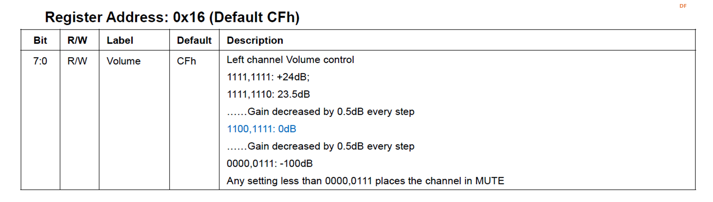
其中的HT513_WriteOneByte(0x16,XX) 是调整音量的代码:
换句话说,有了上面的代码就可以完整的发货出HT513的功能了。
最终完整的代码streams-generator-i2sHT513.ino如下:
- #include <Wire.h>
- #include "AudioTools.h"
-
- AudioInfo info(44100, 1, 16);
- SineWaveGenerator<int16_t> sineWave(32000); // subclass of SoundGenerator with max amplitude of 32000
- GeneratedSoundStream<int16_t> sound(sineWave); // Stream generated from sine wave
- I2SStream out;
- StreamCopy copier(out, sound); // copies sound into i2s
-
- #define HT513_ADDR_L 0x6c
- /**
- @brief ht513写寄存器
- @param addr 寄存器地址
- @param val 要写的值
- @retval None
- */
- void HT513_WriteOneByte(uint8_t addr, uint8_t val)
- {
- Wire.beginTransmission(HT513_ADDR_L);
- Wire.write(addr);
- Wire.write(val);
- int ack = Wire.endTransmission(true);
- Serial.print("Ack ");
- Serial.println(ack, HEX);
- }
-
- /**
- @brief ht513读寄存器
- @param addr 寄存器地址
- @retval 读取到的寄存器值
- */
- uint8_t HT513_ReadOneByte(uint8_t addr)
- {
- uint8_t temp = 0;
-
- Wire.beginTransmission(HT513_ADDR_L);
- Wire.write(addr);
- Wire.endTransmission(false);
- uint8_t bytesReceived = 0;
- bytesReceived = Wire.requestFrom(HT513_ADDR_L, (uint8_t)1, true);
- if (bytesReceived == 1) {
- temp = Wire.read();
- }
- else {
- Serial.println("Read Error ");
- }
-
- return temp;
- }
-
- // Arduino Setup
- void setup(void) {
- Wire.begin(21,22);
- // Open Serial
- Serial.begin(115200);
- while (!Serial);
- AudioLogger::instance().begin(Serial, AudioLogger::Info);
-
- // start I2S
- Serial.println("starting I2S...");
- auto config = out.defaultConfig(TX_MODE);
- config.copyFrom(info);
- out.begin(config);
-
- // Setup sine wave
- sineWave.begin(info, N_B4);
- Serial.println("started...");
-
- int nDevices;
- byte error, address;
- Serial.println("Scanning...");
- nDevices = 0;
- for( address = 1; address < 127; address++ ) {
- Wire.beginTransmission(address);
- error = Wire.endTransmission();
- if (error == 0) {
- Serial.print("I2C device found at address 0x");
- if (address<16) {
- Serial.print("0");
- }
- Serial.println(address,HEX);
- nDevices++;
- }
- else if (error==4) {
- Serial.print("Unknow error at address 0x");
- if (address<16) {
- Serial.print("0");
- }
- Serial.println(address,HEX);
- }
- }
- if (nDevices == 0) {
- Serial.println("No I2C devices found\n");
- }
- else {
- Serial.println("done\n");
- }
-
- // 设置 SD 为LOW
- HT513_WriteOneByte(0x12, 0b11110000);
-
- // 设置数据格式为 I2S, 16Bits
- HT513_WriteOneByte(0x13, 0b00110000);
-
- // 调整音量
- HT513_WriteOneByte(0x16, 0b01111111);
-
- // 设置 SD 为HIGH
- HT513_WriteOneByte(0x12, 0b11110100);
- uint8_t Value = HT513_ReadOneByte(0x12);
- Serial.println("++++++++++++++++");
- Serial.println(Value, HEX);
-
- }
-
- // Arduino loop - copy sound to out
- void loop() {
- copier.copy();
- }
特别注意: HT513 工作时需要 MCLK 信号,因此需要修改库文件 AudioConfig.h
#define PWM_FREQENCY 30000 #define PIN_PWM_START 12 #define PIN_I2S_BCK 14 #define PIN_I2S_WS 15 #define PIN_I2S_DATA_IN 32 #define PIN_I2S_DATA_OUT 18 #define PIN_I2S_MCK 0 #define I2S_USE_APLL true // Default Setting: The mute pin can be switched actovated by setting it to a gpio (e.g 23). Or you could drive the LED by assigning LED_BUILTIN #define PIN_I2S_MUTE -1 #define SOFT_MUTE_VALUE 0 #define PIN_CS SS #define PIN_ADC1 34
本文提到的HT513 测试板电路图和 PCB:
本文使用的测试代码:
工作的视频可以在下面看到:
| 
 创客造
创客造
 编辑选择奖
编辑选择奖
 编辑选择奖
编辑选择奖


 沪公网安备31011502402448

 置顶卡
置顶卡 变色卡
变色卡 千斤顶
千斤顶